Experimenting With Network Topologies
Creating a Network Topology Using Graphviz and the Diagrams Package in Python
Good network documentation starts with a clear topology diagram. In this post, I walk through how I used the Python diagrams library with the graphviz engine to generate a visual topology of my home lab — and share what works well and where it falls short.
After coming across a post about using graphviz with the diagrams Python package, I decided to experiment with it. The toolchain proved useful for rendering simple network flows, and while it doesn't fully capture the complexity of my environment, it's a valuable starting point for documentation and network planning. Below is a walkthrough of how to get started, along with a sample script and the resulting topology diagram.
Tools Used
- Python – Scripting language used to build the topology diagram.
- Graphviz – Graph rendering engine that powers diagram generation.
- Diagrams – Python library for programmatically defining and visualizing infrastructure components.
Installation
Installation is straightforward. Follow the official documentation on the diagrams website.
Windows users: Be sure to add the
Graphviz\bindirectory to your system's user PATH:
- Press
Win + Rand typesysdm.cplto open System Properties. - Navigate to the Advanced tab and click Environment Variables.
- Under User variables, select
Path, then click Edit. - Add a new entry pointing to your Graphviz
bindirectory. - Click OK to save and close the dialogs.
My Graphviz Python Script
from diagrams import Cluster, Diagram
from diagrams.onprem.network import Internet
from diagrams.generic.network import Switch
from diagrams.generic.os import Windows
from diagrams.generic.device import Mobile
from diagrams.onprem.network import Pfsense
from diagrams.onprem.proxmox import Pve
from diagrams.onprem.proxmox import ProxmoxVE
from diagrams.generic.network import Router
from diagrams.generic.network import VPN

with Diagram("TillyNet Home Lab Topology", show=True, direction="LR"):
    internet = Internet("ISP")
    switch = Switch("Catalyst 2960-C")
    openvpn = VPN("OpenVPN Tunnel")

    with Cluster(".\nVirtualizated Stack"):
        pfsense = Pfsense("pfSense FW")
        proxmox = Pve("Hypervisor")

    with Cluster("VLAN 99 - Management"):
        mgmt_pc = Windows("Win Mgmt PC")
        ap_mgmt = Router("EAP670 AP",)
        omada = ProxmoxVE("Omada Controller")
        proxmox_mgmt = Pve("Proxmox Management")

    with Cluster("VLAN 14 - Guest"):
        guest_wifi = Mobile("Guest Devices")

    with Cluster(".\nVLAN 21 - Production"):
        pihole = ProxmoxVE("Pi-hole")

    with Cluster(".\nRemote Management"):
        remote_mgmt = Mobile("Remote Manager")

    # Connections
    internet >> pfsense
    pfsense >> switch
    switch >> [mgmt_pc, omada, proxmox_mgmt, ap_mgmt, pihole]
    ap_mgmt >> guest_wifi
    remote_mgmt >> openvpn
    openvpn >> mgmt_pc
Generated Network Topology
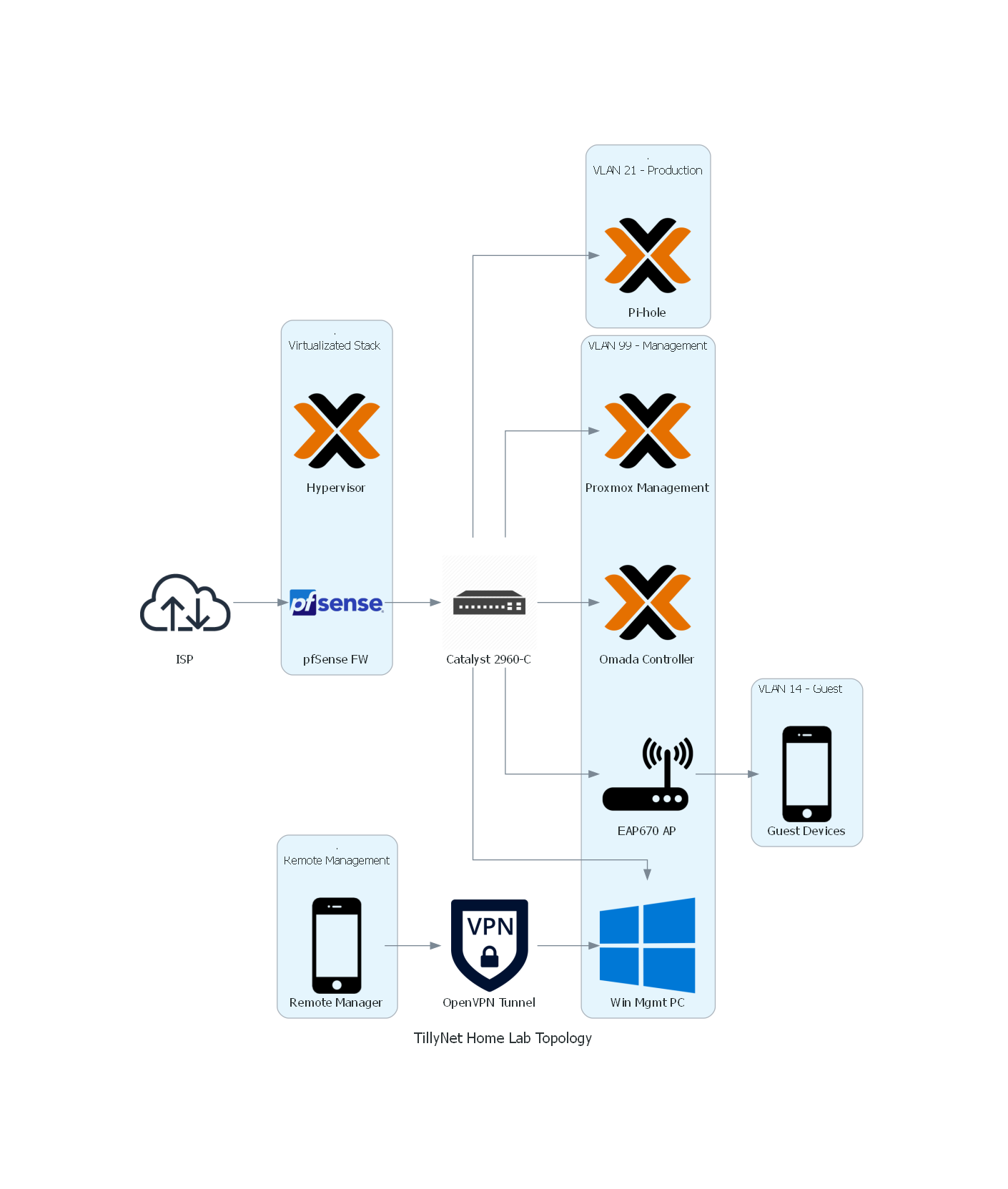
Current TillyNet Home Lab Environment — Summary
The TillyNet home lab is a virtualized, VLAN-segmented network environment designed to simulate enterprise-grade infrastructure and support hands-on experimentation with routing, firewalling, and network automation. It is built around a Proxmox VE hypervisor hosted on a Protectli Vault VP2420, which runs multiple virtual machines and LXC containers to provide core network services.
Key components include:
-
Proxmox VE: Serves as the core hypervisor with both VM and container-based workloads, utilizing PCI passthrough for direct access to physical NICs.
-
pfSense Firewall (VM): Operates as the primary gateway in a router-on-a-stick configuration via a trunked LAN interface to a Cisco Catalyst 2960-C switch. It handles all inter-VLAN routing, DHCP, and firewall policies.
-
VLAN Configuration:
-
VLAN 1 – Native LAN
-
VLAN 14 – Guest network, isolated and tagged for wireless SSID on the access point
-
VLAN 21 – Production network housing internal services like DNS (Pi-hole)
-
VLAN 99 – Management network for administrative access to Proxmox, Omada Controller, and the access point
-
-
Pi-hole (LXC): Runs as the local recursive DNS resolver for the production VLAN.
-
Omada Controller (LXC): Manages the TP-Link EAP670 access point and wireless network provisioning.
-
TP-Link EAP670 (AP): Connected via a trunk port to the Catalyst switch to support both VLAN 14 (guest) and VLAN 99 (management).
-
Cisco Catalyst 2960-C Switch: Provides Layer 2 switching with trunk and access port configurations to support VLAN segmentation and inter-device communication.
This architecture allows for advanced testing of enterprise networking scenarios — including network segmentation, access control, VLAN trunking, recursive DNS, and wireless network integration — all within a self-hosted environment.
Final Thoughts
The diagrams library combined with graphviz is a solid tool for basic network visualization. While it may not be suited for highly detailed or dynamic environments, it offers a clean way to represent logical infrastructure layouts. I plan to continue exploring more advanced or specialized network visualization tools, but this is a strong foundation for documenting my home lab.